Live Dialogs
In Imspector most imaging settings/parameters may be adjusted in live dialogs including activity of devices as lasers and detectors, settings such as laser power or pinhole size and guiding activity along the measurement process such as time lapse measurements.
Live dialogs can be closed individually and re-opened by opening the list in from the main menu and choosing the corresponding dialogs from the list (‘Live Dialogs’ window.). You can toggle the visibility of all live dialogs (with the exception of the ‘Stack display’ live dialog) by pressing the TAB button on the keyboard. Different layouts of live dialogs can be saved as workspaces and quickly restored by selecting from the main menu.
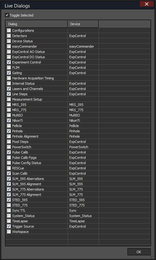
‘Live Dialogs’ window.
Experimental Control Live Dialog
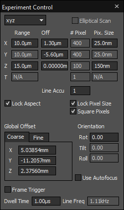
In the ‘Experiment Control’ live dialog (‘Experiment Control’ live dialog.) the basic scan settings are done:
- Type of scan (xy, yx, yz,xz, xt, xyt, xyz …)
- Scan ‘Range’ in X, Y, Z, T
- Local and global offsets of the scanner i.e. the displacement from the central axis. A local offset (given in the upper half of the panel) applies only the current measurement. A global offset applies to all measurements in addition to the local offsets.
- Pixel size (‘Pix. Size’) and the number of pixels (‘# Pixel’)
- Number of scan lines to accumulate (‘Line Accu’)
- Time steps (‘T’): the T-axis in ExpControl allows for fast time-dependent scanning, i.e. for FCS measurements. This will only allow for consecutive time steps. If pauses in between the measurement steps or longer time scales, the Time Lapse Live Dialog has to be used.
- The ‘Orientation’ parameters allow to change the orientation of the scan field: scan field rotation (‘Rot’), tilting of the scan field (‘Tilt’) or rolling of the scan field (‘Roll’) may be applied.
- ‘Dwell Time’ for the individual pixels (only applies if ‘Pixel Steps’ is deactivated)
Note
The Line Frequency (‘Line Freq’) calculated from the scan parameters is given at the bottom right of the dialog. This is only an indicator and cannot be changed directly.
Check boxes
- ‘Lock Aspect’: If selected, the aspect ratio of the scan ranges is locked
- ‘Lock pixel Size’: if selected, the pixel size will be kept constant and the resolution is adjusted on changes of either scan range of pixel size. If it is disabled, the resolution will be kept contant and the pixel size will be adjusted automatically instead.
- ‘Square pixels’: When selected, the pixel sizes in x and y are kept equal.
- ‘Frame trigger’: Allows the start of the measurement to be started on an external signal. The polarity of the signal can be setup in the Hardware Configuration.
- ‘Use Autofocus’: Enables the autofocus module of the microscope (if available)
Note
The scan range may be rounded when the change is incompatible to pixel size and resolution.
‘Experiment Control’ live dialog.
Hardware Acquisition Timing Live Dialog
The measurement timing parameters as ‘Elapsed Time’ for the complete Scan, for the line, frame etc. are given in the ‘Hardware Acquisition Timing’ live dialog (‘Hardware Acquisition Timing’ live dialog.) .
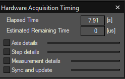
‘Hardware Acquisition Timing’ live dialog.
Lasers and Channels Live Dialog
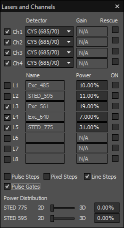
In the ‘Lasers and Channels’ live dialog (‘Lasers and Channels’ live dialog.) is one of the most important live dialogs. Here the user will configure the detection channels and lasers used. Furthermore the advanced imaging modes ‘Pixel Steps’, ‘Line Steps’, ‘Pulse Steps’ and ‘Pulse Gates’ can be activated.
Detectors
(Logical) Detection channels can be activated in the check box on the left side (‘Ch1’, ‘Ch2’, ‘Ch3’, ‘Ch4’), and the corresponding detectors (APDs / PMTs) selected from the drop-down menu. If PMT detectors are selected, the gain of the PMT may be adjusted here. Note that up to four logical (detection) channels can be used.
Lasers
In the middle of the live dialog, the excitation, STED and RESOLFT lasers (‘L1’, ‘L2’, ‘L3’, ‘L4’, ‘L5’, ‘L6’, ‘L7’, ‘L8’) can be activated and their default powers adjusted using the %-values on the right. For alignment purposes, the lasers can be continuously activated using the check box on the right. (This is only possible if the user is logged in as Imspector admin.) Note that the %-values are calibrated to show a linear response in laser power.
Scan Options & Gating
On the bottom of this live dialog, following scan options can be selected: ‘Pulse Steps’, ‘Pixel Steps’ , ‘Line Steps’. Further the fluorescence time-gating for the different detection channels can be activated by selecting ‘Pulse Gates’. Selecting an option will opens its configuration live dialog.
‘Lasers and Channels’ live dialog.
Microscope Control Live Dialogs
Imspector is able to communicate with the microscope stands of several vendors and all of its motorized components. It is able to drive most functions of the microscopy body (Microscope live dialogs for Olympus IX and Nikon Ti eclipse microscopes.). Those functions include:
- switching of the observation mode: allows fast preset-based switching between different microscope configurations (i.e. for scanning, widefield imaging, etc.)
- changing the light path between different ports or the eye pieces
- setting and reading out the stage position (x, y)
- changing objective lenses
- changing filters in filter decks or motorized condensers
- setting and reading out the focus position of the objective lens (z-axis)
- switching on/off the auto-focusing device (optional upgrade)
- brightness of the halogens lamps in the transmitted illumination path (TransIllum) or intensity of fluorescence fiber illumination
- open/close shutters for illumination or auxillary ports
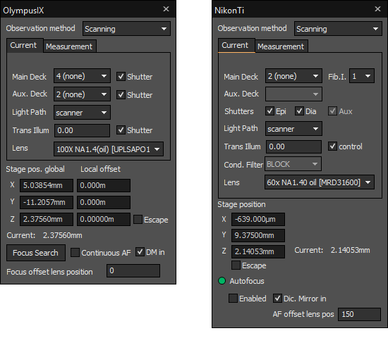
Microscope live dialogs for Olympus IX and Nikon Ti eclipse microscopes.
Time Lapse Live Dialog
In the ‘TimeLapse’ live dialog (‘Time Lapse’ live dialog.), time lapse measurements with breaks in between the individual steps can be devised. More advanced settings with unequal steps can be further devised using the ‘Sequence Scheduler’. ‘Length’ determines the interval, in which the individual measurements are to be taken, i.e. every second. ‘Count’ gives the number of repetions. If the measurement might be longer than the interval, you may activate ‘Ignore timer overflow’ to continue the measurement even if it gets out of sync.
Note
The tool-tips on the usage of the sequence scheduler which can be opened using the question mark at the right side of the live dialog.
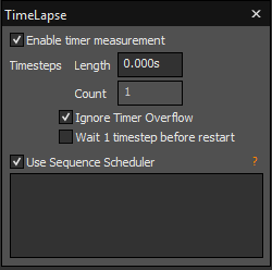
‘Time Lapse’ live dialog.