TCSPC hardware
Introduction
In conjunction with an AI FPGA-based scanner (generally called “Experiment Control”), that is in all AI microscopes, TCSPC hardware from both Becker&Hickl and Picoquant is supported. The documentation here is incomplete and does not replace the training you received when the package was installed on your microscope. This is for advanced users that whish to go beyond simple FLIM measurement or would like to modify the cabeling.
Supported Devices
Supported hardware as of now are the B&H SPC-150, SPC-150N, SPC-160 and SPC-830 cards and the Picoquant TimeHarp260 and HydraHarp 400.
Operating Principle
All hardware is generally driven in FIFO mode and the FIFO data stream in hardware-specific format can generally be written to a file during measurement to allow offline analysis with tools you may have already established while using the component with its generic software. Imspector will control the hardware and supports a growing number of analysis options that should help you make sense of your measurement while it is still going on. It also ensures that you have to enter the measurement geometry only once (instead of making sure that it is synced between AI’s Imspector and the hardware vendor’s program) and that advanced features like pixel- and line-multiplexing are accounted for during channel-sorting.
Generally there will be a physical connection from the AI patch panel to the hardware’s clock and detector inputs and to the marker inputs. At least the “frame enable” and “line enable” signal’s have to be connected.
Settings to be adjusted
Use the “ExpControl DO Status” Live dialog to make sure the connected Patch Panel output actually carries the signal intended. Any output can be used except for those labeled “En <XXX>” which simply enable or disable the patch panel’s AO outputs. All outputs marked with a “+” at the end of their label have 50 Ohm drivers. As an example:
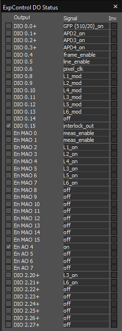
In this case relevant “pixel_clk” is on DIO 0.6, “line_enable” on DIO 0.5 and “frame_enable” on DIO 0.4. Please note that none of them has a 50 Ohm driver, so if your hardware has 50Ohm terminated marker inputs, you may want to use i.e. the free “DIO 2.20+” ff. for this purpose. Also ensure that the cables go from these outputs to the marker inputs of the hardware. In the hardware settings you can now configure which marker carries which meaning and also whether the marker should be switched on and off. This will vary a little between different SPC hardware types but essentially the required settings are similar.
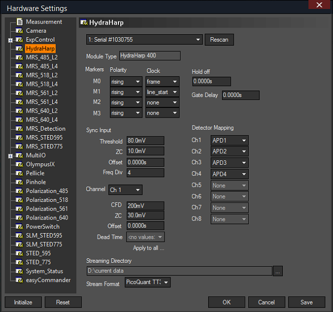
Here, the rising edge of M0 will be interpreted as frame enable, the rising edge of M1 as line enable. M2 and M3 will not be interpreted but are active and will be written to the stream (if disk streaming is enabled in the measurement). All markers that are not on “off” will in fact be written to the stream but Imspector only interprets “line_start”, “frame”, “line_end” and “pixel_clock” to correctly sort data into pixels and channels.
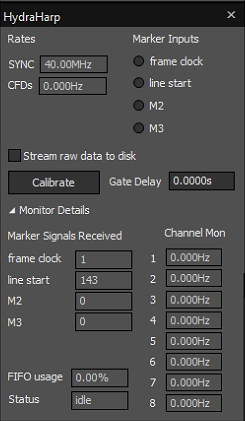
In your TCSPC hardware’s live dialog’s “Monitor Details” section you can see how many markers have been encountered in the current frame. This can help with debugging. In the main section, the LEDs will turn green if markers are encountered. If a marker is expected (i.e. the marker has been configured as “line_start”), the LED will turn red if no marker signal arrives.